Welcome to CHIPTRONIKS Repairing Research Institute Chiptroniks is market leader in Chip Level Repair Training Laptop ,Mobile,LED LCD TV,printer,CCTV Repair Training Institute.(लैपटॉप,मोबाइल, एलईडी एलसीडी टीवी, प्रिंटर, सीसीटीवी रिपेयरिंग ट्रेनिंग सेंटर।)
In this article we will discuss Power Delivery system in Motherboards . For more in depth training , join PCLR Course of chiptroniks or you can also buy our course materials with online support.
Power Delivery
Power delivery—Why & How
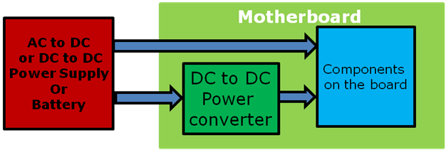
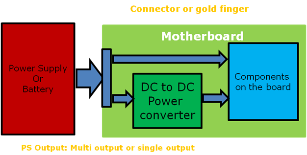
Why: Motherboard components need one or multiple stable and clean DC power to work correctly
How: (1) Power Supply directly to motherboard components (2) for the power which Power Supply can not provide directly, DC to DC power converter on the motherboard converts the power and provide to components
Voltages type needed
Postive DC Voltage: generally between 0V to 12V, generated by DC-DC converter 0.75V, 1.5V, 1.1V… or directly from power supply, like 3.3V, 5V, 12V
Negative DC Voltage: typically -12V
Motherboard voltage normally ranges from -12V to 12V
Tips: General speaking
Higher speed component=> lower voltage needed
(especially for IO function)
Current types needed
Simple answer: Power/voltage=current needed
Low power device: <2A, example: Clock chip, LAN…
Medium power device : between 2A to 50A: example: Fan, DIMM, Chipset
High power device: >50A, example: processor, high power DIMM, high end Graphic card etc
The low/medium/high is just general category, no standard
Tips: High current device has higher requirements on the PCB
Space, layers, cost, copper thickness…, all in all, bigger current,
more design challenge for power designer and CAD engineer
Examples: components Voltage & Current
Processor: 1.0V to 1.5V, 50A to 150A, 130W
DIMM: 1.8V/0.9V for DDR2, 1.5V/0.75V for DDR3, 20A to 40A, 50-100W
Chipset: 1.1V, 10-20A, 5W to 30W
Onboard device: 1.5A, 1-2A, 3.3V, 0.5W to 5W
PCI slot: PCI slot: 12V, 0.5A, 3.3V, 3A, 5V, 1A, 15W, 25W, 75W or more
Fan connector: Depends on fan used, ranges from 0.1A to 5A, 5W to 50W
Tips
Normally 1 Components need multiple voltage rails
depends on what function needed, such as ICH need
1.5V, 3.3V, 1.8V…, more function, more voltage rails needed
For example: ICH has more voltage rail than CPU
due to ICH has more functions
Voltage types by components function
Components may need several voltages by functions: below is general category
(CPU), VDD (DIMM), occupy most the power pin of the components
IO Voltage: Core Voltage: Main voltage for core logic, most of the power consumes on the main voltage) for the core function, example VCCP Voltage for BUS, example: CPU Vtt
Reference Voltage: voltage used for signal sampling
Analog voltage: Some components include analog function, so analog voltage needed, such as Video, PLL circuit, analog voltage require to be clean ! Need to be separated from normal voltage
Components may contain 1 or more type of voltages depends on
Function needed, such as ICH need all 3 above voltages
Voltage types by power state
Some voltage are only required for certain power state
Normal Voltage: Voltage existing when the system is at S0 to S2 state, which means system is at ON state, like CPU main power, fan power, which is main power for the system
Battery Voltage: Voltage existing when the system at AC OFF status, it is powered by onboard battery. Example RTC clock
Standby Voltage: voltage always exists at S0 to S5 state (DC OFF), which means system at DC off state, AC power code is plugged, it is used for board power on/off logic and wake up function and some management function and other functions need to be functional at main power off state, remember, when AC power cord inserted, standby voltage exists !!
Aux Voltage: Voltage switch by between Standby voltage and same Normal Voltage, the main reason of Aux voltage is the function is needed through S0 to S5 state, but standby power can not provide enough current at S0-S2 state due to the device consume more power at S0-S2 state then S3-S5 state, so voltage need switch from standby voltage to normal voltage to get enough current , example: DDR voltage 1.8V, when system is at S3, the Aux voltage comes from 1.8V standby power to keep DIMM refresh, after power on to S0 state, Aux voltage switch to 1.8V normal voltage to support DIMM normal read/write (which consume much more current)
Components may contain 1 or more type of voltages depends on
Function needed, such as ICH need all 4 above voltages
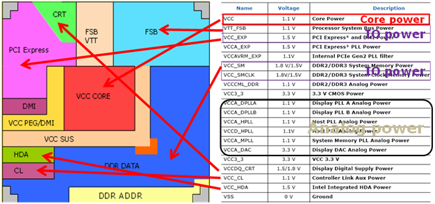
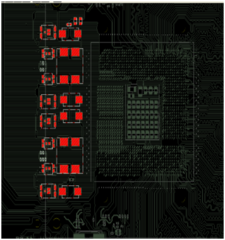
Let us take a look at a real sample-Chipset
G41 MCH (north bridge) function/power mapping
(not exactly correct, just for example)
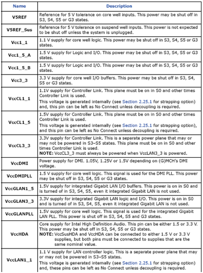
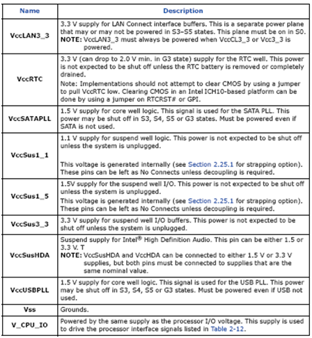
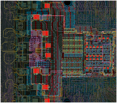
Another example—ICH 10
ICH 10 has require more than 20 voltage rails !! due to lots of functions integrated in ICH 10
Refer to product EDS for pin definition and power requirement
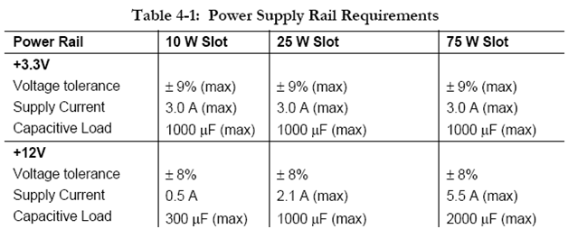
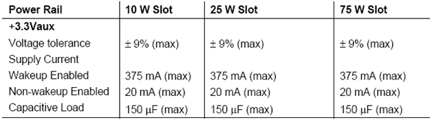
Example 3—PCI-E slot Power requirement
This voltage supply to add in PCI-e card, Card is required to design within this limit
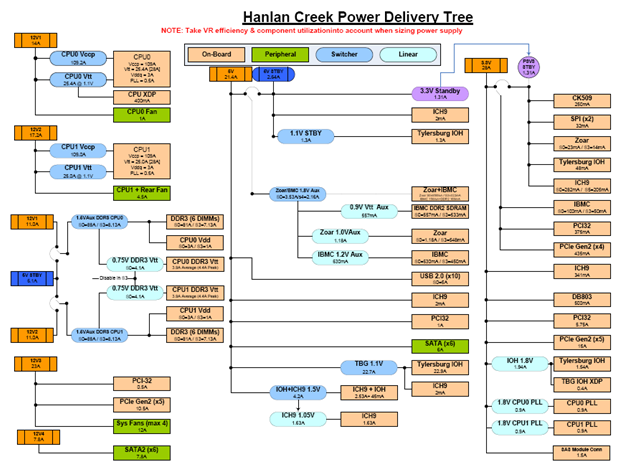
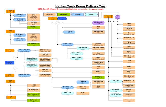
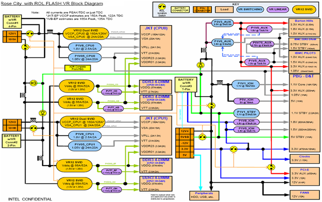
Overall Power Delivery Example–Thurley
Overall Power Delivery Example2—Romley
Motherboard Input Power
Now, we know what kind of power (voltage/Current) needed by components, but where does it come from? Answer: from Power Supply, directly or indirectly
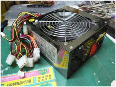
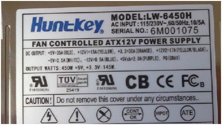
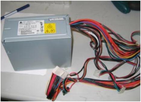
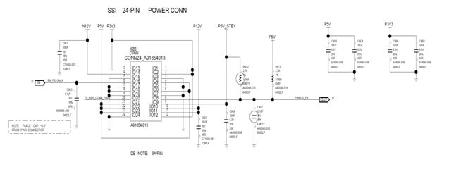
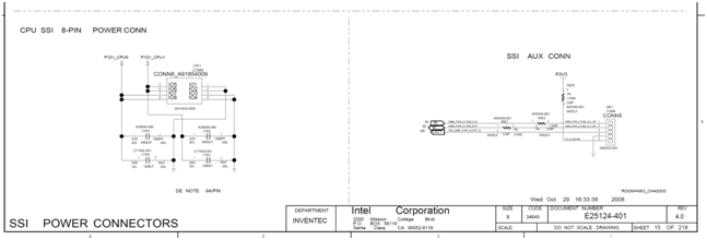
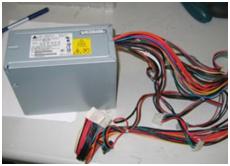
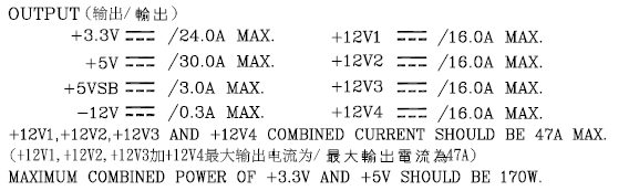
Power Supply Output (motherboard input)
Power Supply output type:
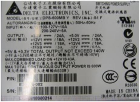
Multiple Output:
Power supply has multiple DC output rail (NOT connector)
Popular 12V, 5V, 3.3V, -12V, 5VSB and other voltage
12V output may have separate rails, like 12V1, 12V2, etc for 240VA protection
Single output: 12V or other voltage only
Power supply has single DC output, 12V is most popular
Battery is single output example
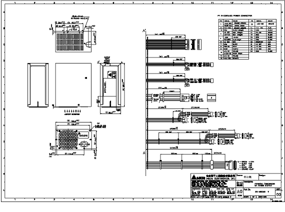
Power Supply output interface:
Connector: board to board or board to cable connector
PCB gold finger: PCB to mating connector
Tips:
Most of single output PSU also has standby output, like 5VSB
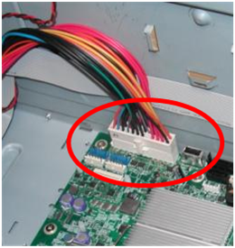
Server EPS12V : Multiple output, cable + connector
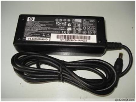
Power Supply Output example 2
Notebook Adapter:
19V Single output, connector, connect to motherboard directly
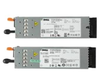
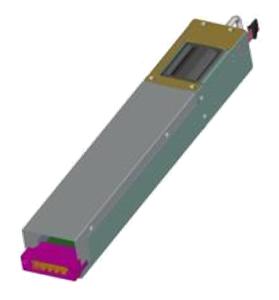
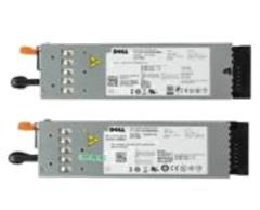
Hotswap module :
12V single output, gold finger and board to board connector
Note:
normally it also has 5VSB output
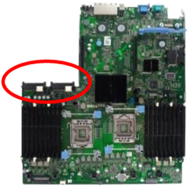
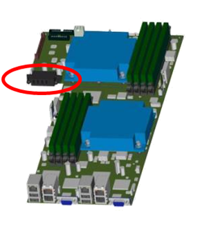
Motherboard side interface
General Rule: mate with power supply output
Connector
Gold finger mating connector
Board to Board connector
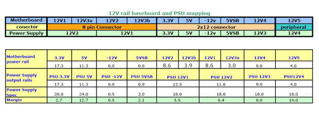
Motherboard power rails & Power supply rails
As we talked before, multiple-output power supply has multiple output, each rail will have current limit, and each rail are separated below is example
Same for motherboard, motherboard will also have multiple rails, like 3.3V, 5V, 12V1, 12V3a…, each rail has current requirement, so we need to mapping the power supply rails to motherboard rails to make sure both power supply & motherboard rails can be met
Next page is example
Rail mapping Example
Power supply connector/rail mapping
Caution:
Power supply rail can be separate to support multiple
motherboard rail, but reverse is NOT allowed!, otherwise it will
Short power supply rails and cause protection
DC to DC converter
So far, we know how power supply provide voltage rail to motherboard, like 12V, 5V 3.3V, etc by connectors or PCB gold finger or other method, but for the other voltage power supply can not provide, like 1.1V, 1.5V, 0.8V, we need DC to DC converter on the motherboard to convert the power supply voltage to the voltage we needed
DC to DC converter also called Voltage regulator (VR)
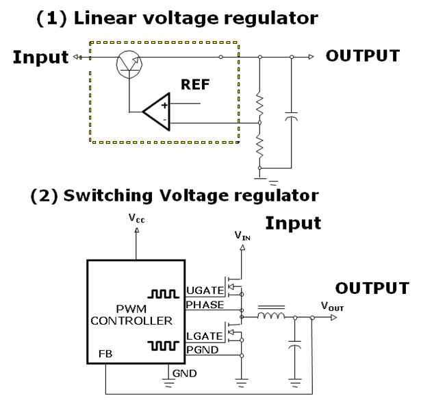
DC to DC converter (VR) types
(1) Linear voltage regulator
-Low current
-Low efficiency
-Low cost
-Simple
-Clean (little noise)
-High current
-High efficiency
-High cost
-Complex
-High noise
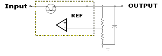
Linear VR
–
Simple & Clean (little noise)
-Low current
-Low voltage drop
-Low efficiency
-Low cost
(1) Why low current and low voltage drop?
vdrop on the VR= Vout-Vin, so the power loss = I x Vdrop, for example: Vin=3.3V, Vout=1.5V, 2A, so the power loss on converter is (3.3-1.5)x2=3.6W, assume 50C/W, so the temp rise will be 150C, which is burn the components, so only low current and low voltage is allowed, Linear VR only support low current requirement
(2) Why low efficiency?
The efficiency= output power/input power, obvious, it is low efficiency due to the power loss on the converter is big, the bigger difference between Vin and Vout, the lower efficiency is.
(3) Why simple & clean & low cost
It is simple & due to just a few components needed
It is clean due to no switch components, it is easier to place & layout the linear VR
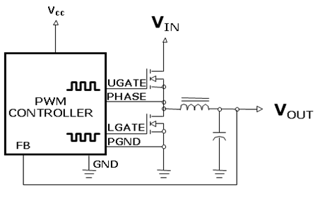
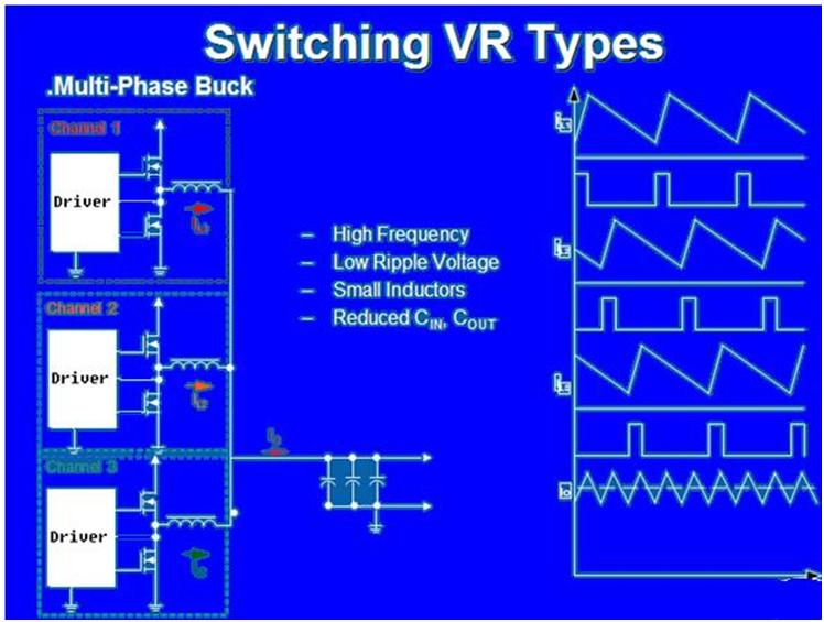
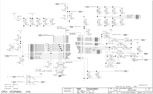
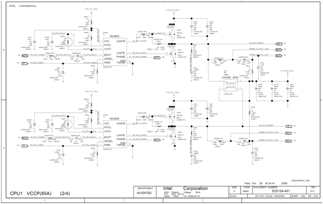
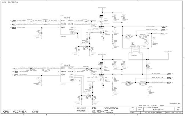
Switching VR Types—Single Phase
-High current
-High efficiency
-High cost
-Complex
-High noise
Basic working principal is by control the mosfet PWM value to adjust the output voltage, Vout/Vin=PWM%, for example: 12V to 1.5V, PWM=12.5%
Switching VR efficiency is between 80 to 98% depends on VR design, the main power loss is VR Mosfet switching & conduct loss
It can handle high current due to high efficiency
High cost /complex is obvious: it need chip, mosfet, inductor, capacitor…
High noise: due to switching method and mosfet switching, it has much higher noise than linear regulator
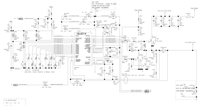
We will NOT discuss how VR works here, refer to VR training slides
if you are interested, Overall speaking, VR is a complex technology
sorry to say not well explained since many topics but well documented manythings overall was very good but only for those who have in-depth knowledge of complex Integrated circuits.


sorry to say not well explained since many topics but well documented manythings overall was very good but only for those who have in-depth knowledge of complex Integrated circuits.