In this article we will deal with basic electronics which is very essential for mobile repairing . Chiptroniks has emerged as the clear leader in offering quality mobile repairing course . Recently we opened our first centre in Shillong . So guys now we are opening up anybody interested to have our Franchisee can contact us .
Mobile repairing is a combination of 2 things:
- Hardware
- Software

Q. What is an Atom?
A. An Atom is a smallest part of an Element which cannot be divided further. Examples are Solid, Liquid and Gaseous States.
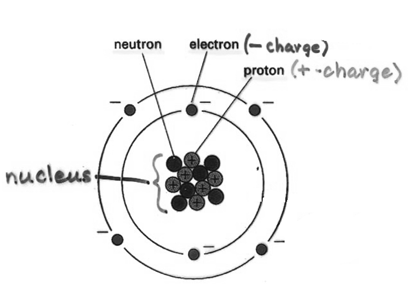
Q. What is Voltage?
A. Voltage is the force of electrons and the unit is measured in Volts. Circuit Representation of voltage is (V).
The unit of current is measured in Amperes. The Circuit Representation of Current is (I).
Dropping of voltage is called as Resistance. Ohms is the unit of Resistance Ω. Circuit Representation of Resistance is ®.


 Ohms Law


The current flowing in the circuit is directly proportional to the voltage but inversely proportional to the Resistance.
Ex.1. If voltage is 250 AC and the current is 5 Amperes calculate Resistance.
Ans: Using formula R=
 -> R=
-> R=  Ω
Ω
Ex.2. If the voltage is 3.6 V DC and the current is 400 mA calculate resistance.
Ans: Using formula R=
 -> R=
-> R=  Ω
Ω
Study of Multi-meter
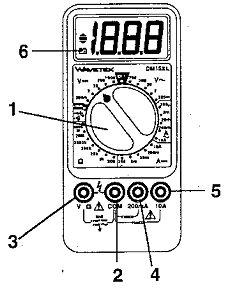
- Function/Range Switch: selects the function (voltmeter, ammeter, or ohmmeter) and the range for the measurement.
- COM Input Terminal: Common ground, used in ALL measurements.
- V Input Terminal: for voltage or resistance measurements.
- 200 mA Input Terminal: for small current measurements.
- 10A Input Terminal: for large current measurements.
- Low Battery LCD: appears when the battery needs replacement.
Precautions for Current Measurements
Precautions for Resistance Measurements
- Turn the power off to the device and discharge any capacitors!
- Plug the black test lead into the COM jack.
- Plug the red test lead into the V
 jack.
jack.
- Set the function/range switch to ohms (
 ) in the lower left.
- If you do not know the approximate resistance about to be measured, use the largest range available.
- Connect the free ends of the red and black test leads ACROSS the device to the measured. Resistance is always measured with the meter in PARALLEL with the device.
- If the LCD displays either “1.” or “-1.” with all other digits blank, the resistance is beyond the selected range. Use the switch to select a larger range.
- Once you know the approximate resistance of the device, then use the switch to select the lowest range that will still accommodate the resistance of the device.
Voltages
There are two types of voltages:
- Alternate Current (AC)
- Direct Current (DC)
AC current is a high voltage and contain frequency of 50Hz means that in a second it goes 50 times in positive and negative cycle.
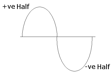
Direct Current (DC) is a low voltage. Examples are Batteries (1.5 V to 24 V). It doesn’t have frequency in it.
Frequency is defined as Number of cycles per seconds.
Conventional current is a flow of current from +ve to –ve direction
Electronic Components
Electronic components are divided into two categories:
-
Passive Components
-
Active Components
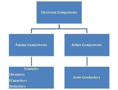
The active component changes the entire function of the circuit. The examples of this are Semi-Conductors (AC to DC)
The passive component doesn’t have the ability to change the function of the circuit. It only modifies and re-modifies their respective circuits. The examples of passive components are as follows:
-
Resistors
-
Capacitors
-
Inductors
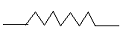
Resistors
Resistors are the electronic component which is used to drop the voltages. There are 3 types of Resistors:
|
Resistor Type
|
Symbol
|
Circuit Symbol
|
| 1 |
Fixed Carbon (color Coded) |
 |
 |
| 2 |
Variable |
 |
|
| 3 |
Fusable |
 |
|
Resistor Values
Resistor values that are available for use in circuits range from 0 to around 10,000,000
 . Because dealing with large numbers like 10,000,000 is awkward, the ‘k’ prefix is used to denote 1,000 and the ‘M’ prefix is used to denote 1,000,000. ‘k’ stands for ‘kilo’ and ‘M’ stands for mega. Here are some examples of resistor values:
1k = 1,000
 (pronounced ‘one kilo Ohm’ or ‘one k’ for short)
10M = 10,000,000
 (pronounced ‘ten mega Ohms’ or ‘ten meg’ for short)
Sometimes you will see resistors quoted without the  symbol, and sometimes the symbol will be replaced with ‘R’. When a fraction is needed in a value you will often see ‘R’, ‘k’, or ‘M’ in place of the decimal point as an aid to clarity:
22k is the same as 22k
330R is the same as 330
4K7 is the same as 4.7k
Tolerance
Like all components, resistors are never perfect. Their true value will never be exactly the same as their stated value, but will be somewhere close. The maximum amount of error in the value is given by the ‘tolerance’ value, expressed as a percentage. Most resistors have a 10% – 20% tolerance, and this is normally adequate for most applications. You can get 1% and 2% tolerance resistors if you need them.
The Resistor Colour Code
Because resistors are so small, it is not easy to print their value and tolerance on them in a way which is easily readable. Therefore, one of the following colour coding systems is used instead. Both systems code the value in Ohms – there are no codes for ‘k’ or ‘M’.
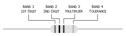
The Four-Band System
This system uses three coloured bands to represent a resistor’s value, and an additional coloured band spaced further apart to represent a resistor’s tolerance, as shown in figure 2.
- The first two bands give the the first two digits of the resistor’s value.
- The third band is a multiplier and gives the number of zeroes that must be placed after the first two digits.
- The forth band gives the resistor’s tolerance as a percentage.
The table below shows the meaning of each colour for each of the bands. Notice that most of the colours are in the order of the colours of a rainbow, with the exception of indigo which is not used. There is a rhyme you can use to remember these colours: Richard Of York Gave Battle in Vain.
|
Colour
|
Band 1
1st Digit
|
Band 2
2nd Digit
|
Band 3
Multiplier
|
Band 4
Tolerance
|
|
Black |
0
|
0
|
x 1 |
–
|
|
Brown |
1
|
1
|
x 10 |
–
|
|
Red |
2
|
2
|
x 100 |
–
|
|
Orange |
3
|
3
|
x 1,000 |
–
|
|
Yellow |
4
|
4
|
x 10,000 |
–
|
|
Green |
5
|
5
|
x 100,000 |
–
|
|
Blue |
6
|
6
|
x 1,000,000 |
–
|
|
Violet |
7
|
7
|
x 1,000,0000 |
–
|
|
Grey |
8
|
8
|
x 1,000,00000 |
–
|
|
White |
9
|
9
|
x 1,000,000000 |
–
|
|
Gold |
–
|
–
|
–
|
+/- 5%
|
|
Silver |
–
|
–
|
–
|
+/- 10%
|
Exercise:
| 1) |
Band1= Brown
Band2= Black
Band3= Brown |
1
0
0 |
100 Ω |
|
|
|
|
| 2) |
Band1= Red
Band2=Red
Band3=Red |
2
2
00 |
2200 Ω = 2.2 K Ω |
|
|
|
|
| 3) |
Band1=Orange
Band2=Orange
Band3=Orange |
3
3
000 |
33000 Ω = 33 K Ω |
|
|
|
|
| 4) |
Band1=Brown
Band2=Black
Band3=Yellow |
1
0
0000 |
100000 Ω = 100 K Ω |
|
|
|
|
| 5) |
Band1=Orange
Band2=Red
Band3=Blue |
3
2
000000 |
32000000 Ω = 32 M Ω |
|
|
|
|
| 6) |
Band1=Yellow
Band2=Violet
Band3=White |
4
7
000000000 |
47000000000 Ω = 47000 M Ω |
|
|
|
|
| 7) |
Band1=Green
Band2=Blue
Band3=Grey |
5
6
00000000 |
5600000000 Ω = 5600 M Ω |
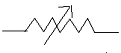
Variable Resistors
 Variable Resistors are used to increase and decrease the resistances. The examples in this category are as follows:
-
Volume Control Knob
-
Fan Regulator
Fusable Resistor
The function of fusable resistor is to break the circuit when excess current flows above its specification
Inductors
Inductors are divided into two categories viz.
- Coils
- Transformers
 Coils
Coils
Symbol:
Circuit Representation: (L)
Unit of Measurement: Henry
The function of coil is to filter the voltage. When voltage is applied to a coil EMF (Electro Motive Force) is generated.
Transformers
The function of transformer is to transform on energy into another. It steps up and down the voltage. Every electronic and electrical device has their specification mentioned on the back panel on their respective bodies. So for replacement of the Transformer of a particular device if it gets faulty, the same value unit of transformer should be replaced.
Transformers are further divided into two categories viz.
-
Step-Up (Example: EHT (Extra High Tension)
-
Step-Down
Step-Down Transformer
Step-down transformers are further divided into two categories:
-
Conventional
-
Center-Tap Transformer
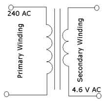 Conventional Transformer
low voltage is passed from primary to secondary winding. For Example, a step down transformer of 4.6 V AC requires 240 V AC at the primary winding which is stepped down to 4.6 V AC at the secondary winding.
To find out which is the primary and secondary winding in Conventional Transformer use Multi meter and keep it in buzzer mode. Place the testing probes on either side, if buzzer is heard then that is Secondary Winding.
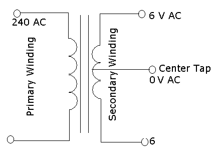
Center-Tap Transformer
Center-tap Transformer has a center winding of 0 V, in other words we can say that the secondary winding contains 3 wires, the center on is 0 Volts. Refer the diagram for more.
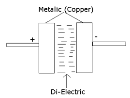
Capacitors
The function of capacitor is to pass the AC voltage and store the DC voltage. Capacitors are further divided into two categories:
-
Polarized
-
Non-Polarized
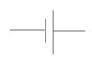
Polarized Capacitors
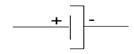
Symbol:
Looks:
Unit: Micro Fared (µf)
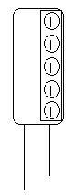
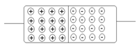
Internals of Electrolytic Capacitors
Non-Polarized Capacitors
Symbol:

Looks:
Non-polarized capacitors are disc or ceramic capacitors. The unit is Pico fared.
Semi Conductors
Semi conductors are the elements which are partly conductors and partly insulators. Example of element is Silicon. The examples of semi-conductors are as follows:
-
Diodes
-
Transistors
-
I.C. (Integrated Circuits)
Diodes
Diodes are semi conductor components which converts AC to DC (Rectifier Ciruits). It has 3 major components:
-
P.N. Junction
-
Zener Diode
-
L.E.D. (Light Emitting Diode)
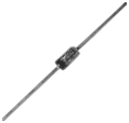
P.N. Junction Diode

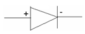
Symbol: Layout:
Internals:
When we check a diode on a multi meter on buzzer mode, by placing the red probe on the positive side and black probe on the negative side, we hear buzzer. It means that the diode is Forward Bias. If we place the testing probe in the reverse order, we do not hear buzzer, it means that the diode is reverse bias. It indicates that diode works in one direction i.e. from Positive to negative which is called as Forward Bias. P.N. Junction diodes convert AC to DC (Rectifier Circuit)


 Zener Diode
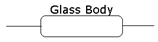
Symbol: Layout:
Zener diode acts as a voltage stabilizer. It comes under different voltages such as 5 V, 10 V, 12 V etc.
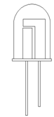 L.E.D. (Light Emitting Diode)
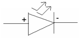
Symbol: Layout:
The function of LED is that it emits light when voltage is passed to it. It is used as a power indicator in the circuit. It operates under 1.5 V DC and comes under different colors such as Red, Yellow, Green, Blue.
Rectifier Circuits
Rectifiers are the circuit which converts AC to DC voltage. The are 3 types of Rectifier Circuits:
-
Half Wave Rectifier
-
Full Wave Rectifier
-
Bridge Rectifier
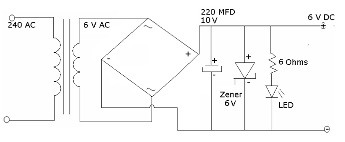
Half Wave Rectifier (Preparation of Mobile Charger)
Requirements to make Half Wave Rectifier
-
Conventional Transformer 6 V AC / 1 Amp.
-
PN Junction Diode (1 Nos.)
-
Electrolytic Capacitor 10V/220 MFD
-
Zener Diode
-
Resistor (Voltage Drop at LED)
-
LED (Power Indicator)
Circuit Diagram
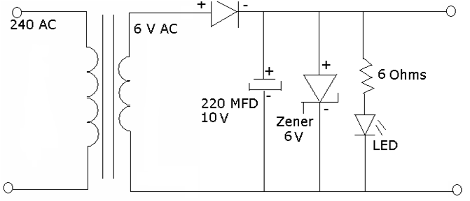
Preparation of Mobile Charger
The Half Wave Rectifier is a circuit which converts AC to DC voltage. In this circuit, only one P.N. Junction Diode is used. The internal Resistance of Primary Winding of a transformer is very high because of this the voltage is dropped to 6 volts AC. In between the core of Primary Winding and Secondary Winding, EMF is generated and the voltage is transferred to the secondary winding. At the output of secondary winding, we get step down voltage of 6 V AC form (It will have 50 Hz. Frequency).
So a PN Junction Diode is connected in series. The diode will only forward bias the positive half cycle of AC voltage. But there are chances of AC Leakage (Ripples) which may damage the battery at the time of charging. Therefore, an Electrolytic Capacitor is used to bypass DC and block AC voltage.
A Zener Diode is used to stabilize the voltage. It is of 6 V. The Zener diode will start working when more than 6V is applied to it. It will break the circuit when excess voltage comes. LED is used as a power indicator and a Resistor is attached to it to drop the voltage because LED works on 1.5 V and our circuit is of 6V.
Hence a charger is prepared successfully.
Full Wave Rectifier
Requirements to make Full Wave Rectifier
-
Center Tap Transformer 6-0-6 V AC / 1 Amp.
-
PN Junction Diode (2 Nos.)
-
Electrolytic Capacitor 10V/220 MFD
-
Zener Diode
-
Resistor (Voltage Drop at LED)
-
LED (Power Indicator)
Circuit Diagram
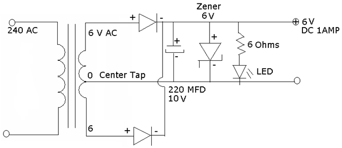
With Respect to half wave rectifier this gives better performance because at the same time 2 diodes are Forward Bias so we get double positive half cycle. This minimizes the AC Leakage chances. Rest of the circuit is same.
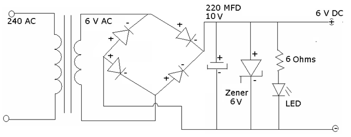
Bridge Rectifier
Requirements to make Bridge Wave Rectifier
-
Conventional Transformer 6 V AC / 1 Amp.
-
PN Junction Diode (4 Nos.) or Bridge Rectifier Module.
-
Electrolytic Capacitor 10V/220 MFD
-
Zener Diode
-
Resistor (Voltage Drop at LED)
-
LED (Power Indicator)
Circuit Diagram (Using PN Junction Diodes)
Circuit Diagram (Using Bridge Rectifier Module)
 Bridge Rectifier gives the same performance of the full wave rectifier. This circuit can be prepared by using conventional tansformer using Bridge Rectifier Module and rest remain same.
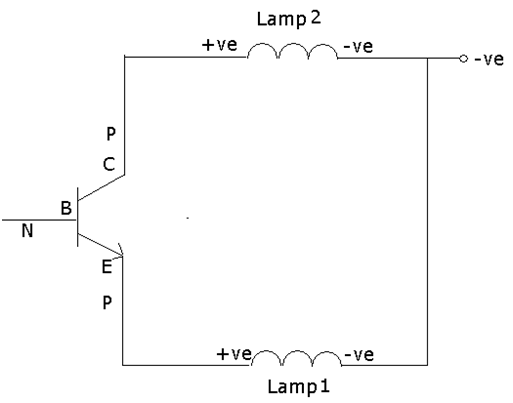
Transistors
Transistor acts as an open switch. The input voltage is a form of AC which is given to the base of Transistor. Transistor are used for amplification of the signal (Convert Weak signals into stronger signals)
Transistors are further divided into 2 categories:
-
NPN
-
PNP
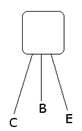
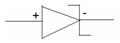
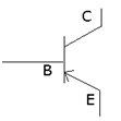
NPN Transistors
Symbol: Layout:
When we check a NPN transistor on a Multimeter by keep the red probe on the base of the transistor and the black probe on either Collector or Emitter, we can hear buzzer. This indicates the following:
-
Base to Collector: Forward Bias
-
Base to Emitter: Forward Bias
When do this in reverse order, we do not hear buzzer. This indicates the following:
-
Base to Collector: Reverse Bias
-
Base to Emitter: Reverse Bias
Example Circuit:
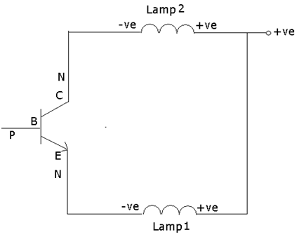
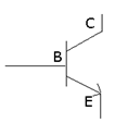
 PNP Transistor
Symbol: Layout:
This is an exact opposite of NPN Transistor. When we check it using Multimeter by keeping the Black Probe on the base and Red probe on either Collector or Emitter, we hear buzzer. This indicates the following:
-
Base to Collector: Forward Bias
-
Base to Emitter: Forward Bias
When do this in reverse order, we do not hear buzzer. This indicates the following:
-
Base to Collector: Reverse Bias
-
Base to Emitter: Reverse Bias
 Example Circuit:
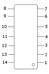
I.C. Integrated Circuits
Integrated Circuits have many inbuilt components in it and it is designed as per the circuit requirements. There are 2 types of I.C.
-
PGA (Pin Grid Architecture)
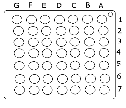
-
BGA (Ball Grid Architecture)
All the major sections in the Electronic devices are controlled by IC’s. For Example,Mobile’s Charging, Power, Network, Audio sections etc.
Most of the faults in the electronic devices are because of IC’s. They have most of the load on them.
|
PGA (Pin Grid Architecture)
|
BGA (Ball Grid Architecture)
|
|
|
|
Soldering Techinques
Soldering is a process of making and breaking the soldering contacts of the electronic components. It is done by the equipment called as Soldering Iron. There are two types of soldering irons:
-
25 Watt High Power AC Iron
-
Micro Tip DC Iron
Accessories Required for Soldering:
-
Solder Wire (Trip 60/40 i.e. 60% Aluminium and 40% Tin)
-
Liquid Soldering Paste / Soldering Flux


these notes are very useful and beneficial to students.
useful basic information for mobile repairing
Dear Sunil,
Thank you for contacting CHIPTRONIKS .
You have been replied by chiptroniks counsellor
Regards,
TEAM CHIPTRONIKS
lern mobile technic
i am astudent
very usefuk for information
very very useful post I am an associate engineer in electronics.
hello sir,
how r u i m from jammu and i did mobile reparing from chiptroniks last year.
now i am doing mobile reparing at jammu.
thanks for knowledge.
I have read so many articles regarding the blogger lovers except this paragraph is really a good article, keep it up.
nice……………………………..but ok!
i want to no about mobile.
i want to know about mobile
i want to know even more about mobile thz
very good explanation without any confustion in simple language. Thank u
Nice
You do not need to possess a telephone land line to reap the benefits of
a wireless home alarm system. If you enjoyed this article by Jeff Schuman please
be sure to drop by and visit our home security website
today. As we all know, during the hot summer our home fills with
the hot sun rays and become more warm and hot but
with these privacy films, you can block the entrance of harsh day light to control temperature inside your house.
send in mobile reparing theory in hindi
HI..
great knowledge given by chiptroniks one should follow who is learning mobile repair one is blind to learn mobile repair course with out basis electronic I one more thanks for chiptroniks